
静态路由怎么配置图解,静态路由配置详细教程
1、实验目的
掌握如下技能:
(1) 路由表的概念
(2) ip route 命令的使用
(3) 根据需求正确配置静态路由
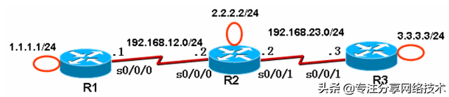
2. 实验拓扑

3. 实验步骤
我们要使得 1.1.1.0/24、2.2.2.0/24、3.3.3.0/24 网络之间能够互相通信。
(1) 步骤 1:在各路由器上配置 IP 地址、保证直连链路的连通性
R1(config)# int loopback0
R1(config-if)# ip address 1.1.1.1 255.255.255.0
R1(config)# int s0/0/0
R1(config-if)# ip address 192.168.12.1 255.255.255.0
R1(config-if)# no shutdown
R2(config)# int loopback0
R2(config-if)# ip address 2.2.2.2 255.255.255.0
R2(config)# int s0/0/0
R2(config-if)# clock rate 128000
R2(config-if)# ip address 192.168.12.2 255.255.255.0
R2(config-if)# no shutdown
R2(config)# int s0/0/1
R2(config-if)# clock rate 128000
R2(config-if)# ip address 192.168.23.2 255.255.255.0
R2(config-if)# no shutdown
R3(config)# int loopback0
R3(config-if)# ip address 3.3.3.3 255.255.255.0
R3(config)# int s0/0/1
R3(config-if)# ip address 192.168.23.3 255.255.255.0
R3(config-if)# no shutdown
(2) 步骤 2:R1 上配置静态路由
R1(config)# ip route 2.2.2.0 255.255.255.0 s0/0/0
//下一跳为接口形式,s0/0/0 是点对点的链路,注意应该是 R1 上的 s0/0/0 接口
R1(config)# ip route 3.3.3.0 255.255.255.0 192.168.12.2
//下一跳为 IP 地址形式,192.168.12.2 是 R2 上的 IP 地址
(3) 步骤 3:R2 上配置静态路由
R2(config)# ip route 1.1.1.0 255.255.255.0 s0/0/0
R2(config)# ip route 3.3.3.0 255.255.255.0 s0/0/1
(4) 步骤 4:R3 上配置静态路由
R3(config)# ip route 1.1.1.0 255.255.255.0 s0/0/1
R3(config)# ip route 2.2.2.0 255.255.255.0 s0/0/1
4. 实验调试
(1) 在 R1、R2、R3 上查看路由表
R1# show ip route
Codes: C – connected, S – static, R – RIP, M – mobile, B – BGP
D – EIGRP, EX – EIGRP external, O – OSPF, IA – OSPF inter area
N1 – OSPF NSSA external type 1, N2 – OSPF NSSA external type 2
E1 – OSPF external type 1, E2 – OSPF external type 2
i – IS-IS, su – IS-IS summary, L1 – IS-IS level-1, L2 – IS-IS level-2
ia – IS-IS inter area, * – candidate default, U – per-user static route
o – ODR, P – periodic downloaded static route
Gateway of last resort is not set
C 192.168.12.0/24 is directly connected, Serial0/0/0
1.0.0.0/24 is subnetted, 1 subnets
C 1.1.1.0 is directly connected, Loopback0
2.0.0.0/24 is subnetted, 1 subnets
S 2.2.2.0 is directly connected, Serial0/0/0
3.0.0.0/24 is subnetted, 1 subnets
S 3.3.3.0 [1/0] via 192.168.12.2
2.0.0.0/24 is subnetted, 1 subnets
S 2.2.2.0 is directly connected, Serial0/0/0
3.0.0.0/24 is subnetted, 1 subnets
S 3.3.3.0 [1/0] via 192.168.12.2
R2# show ip route
Codes: C – connected, S – static, R – RIP, M – mobile, B – BGP
D – EIGRP, EX – EIGRP external, O – OSPF, IA – OSPF inter area
N1 – OSPF NSSA external type 1, N2 – OSPF NSSA external type 2
E1 – OSPF external type 1, E2 – OSPF external type 2
i – IS-IS, su – IS-IS summary, L1 – IS-IS level-1, L2 – IS-IS level-2
ia – IS-IS inter area, * – candidate default, U – per-user static route
o – ODR, P – periodic downloaded static route
Gateway of last resort is not set
C 192.168.12.0/24 is directly connected, Serial0/0/0
1.0.0.0/24 is subnetted, 1 subnets
S 1.1.1.0 is directly connected, Serial0/0/0
1.0.0.0/24 is subnetted, 1 subnets
S 1.1.1.0 is directly connected, Serial0/0/0
2.0.0.0/24 is subnetted, 1 subnets
C 2.2.2.0 is directly connected, Loopback0
3.0.0.0/24 is subnetted, 1 subnets
S 3.3.3.0 is directly connected, Serial0/0/1
3.0.0.0/24 is subnetted, 1 subnets
S 3.3.3.0 is directly connected, Serial0/0/1
C 192.168.23.0/24 is directly connected, Serial0/0/1
R3# show ip route
Codes: C – connected, S – static, R – RIP, M – mobile, B – BGP
D – EIGRP, EX – EIGRP external, O – OSPF, IA – OSPF inter area
N1 – OSPF NSSA external type 1, N2 – OSPF NSSA external type 2
E1 – OSPF external type 1, E2 – OSPF external type 2
i – IS-IS, su – IS-IS summary, L1 – IS-IS level-1, L2 – IS-IS level-2
ia – IS-IS inter area, * – candidate default, U – per-user static route
o – ODR, P – periodic downloaded static route
Gateway of last resort is not set
1.0.0.0/24 is subnetted, 1 subnets
S 1.1.1.0 is directly connected, Serial0/0/1
2.0.0.0/24 is subnetted, 1 subnets
S 2.2.2.0 is directly connected, Serial0/0/1
1.0.0.0/24 is subnetted, 1 subnets
S 1.1.1.0 is directly connected, Serial0/0/1
2.0.0.0/24 is subnetted, 1 subnets
S 2.2.2.0 is directly connected, Serial0/0/1
3.0.0.0/24 is subnetted, 1 subnets
C 3.3.3.0 is directly connected, Loopback0
C 192.168.23.0/24 is directly connected, Serial0/0/1
(2) 从各路由器的环回口 ping 其他路由器的环回口:
R1# ping
//不带任何参数的 ping 命令,允许我们输入更多的参数
Protocol [ip]:
Target IP address: 2.2.2.2 //目标 IP 地址
Repeat count [5]: //发送的 ping 次数
Datagram size [100]: //ping 包的大小
Timeout in seconds [2]: //超时时间
Extended commands [n]: y //是否进一步扩展命令
Source address or interface: 1.1.1.1 //源 IP 地址
Type of service [0]:
Set DF bit in IP header? [no]:
Validate reply data? [no]:
Data pattern [0xABCD]:
Loose, Strict, Record, Timestamp, Verbose[none]:
Sweep range of sizes [n]:
Type escape sequence to abort.
Sending 5, 100-byte ICMP Echos to 2.2.2.2, timeout is 2 seconds:
Packet sent with a source address of 1.1.1.1
!!!!!
Success rate is 100 percent (5/5), round-trip min/avg/max = 12/14/16 ms
//以上说明从 R1 的 loopback0 可以 ping 通 R2 上的 loopback0。也可以直接使用命令:
R1# ping 2.2.2.2 source loopback 0
Type escape sequence to abort.
Sending 5, 100-byte ICMP Echos to 2.2.2.2, timeout is 2 seconds:
Packet sent with a source address of 1.1.1.1
!!!!!
Success rate is 100 percent (5/5), round-trip min/avg/max = 12/14/16 ms
R2# ping 1.1.1.1 source loopback 0
R2# ping 3.3.3.3 source loopback 0
//从 R2 的 loopback0 应该可以 ping 通 R1 和 R3 的 lopback0 接口。
R3# ping 1.1.1.1 source loopback 0
R3# ping 2.2.2.2 source loopback 0
//从 R3 的 loopback0 也应该可以 ping 通 R1 和 R2 的 lopback0 接口。
【提示】虽然从 R1 的 loopback0 可以 ping 通 R3 的 loopback0,数据需要经过
192.168.23.0/24 网络,但是在 R1 上我们并没有添加 192.168.23.0/24 的路由。路由器转
发数据包完成是根据路由表的,并且数据是一跳一跳地被转发的,就像接力赛似的。从 R1
的loopback0口ping R3的loopback0口时,IP数据包的源IP为1.1.1.1,目的IP为3.3.3.3。
R1 路由器首先查路由表,数据包被发到了 R2;R2 路由器也查路由表(3.3.3.0/24 路由),
数据包被发到了 R3;R3 知道这是直连路由。R3 响应 R1 的数据包进行类似的过程。
(3) 从 R1 上 ping 2.2.2.2、从 R1 上 ping 3.3.3.3
R1# ping 2.2.2.2
Type escape sequence to abort.
Sending 5, 100-byte ICMP Echos to 2.2.2.2, timeout is 2 seconds:
!!!!!
Success rate is 100 percent (5/5), round-trip min/avg/max = 12/14/16 ms
//可以 ping 通。
R1# ping 3.3.3.3
Type escape sequence to abort.
Sending 5, 100-byte ICMP Echos to 3.3.3.3, timeout is 2 seconds:
…..
Success rate is 0 percent (0/5)
//以上无法ping通,原因在于使用ping命令时,如果不指明源接口,则R1路由器使用s0/0/0
接口的 IP 地址(192.168.12.1)作为 IP 数据包的源 IP 地址了。R3 上响应 R1 的数据包时,
数据包是发向 192.168.12.1 的,然而由于 R3 没有 192.168.12.0/24 的路由,数据包无法发
送。即:数据包从 R1 到了 R3 后,无法返回 R1。
5. 静态路由
在实验 1 的基础上进行
(1) 步骤 1:R1、R3 上删除原有静态路由
R1(config)# no ip route 2.2.2.0 255.255.255.0 Serial0/0/0
//要删除路由,在原有命令前面加 no 即可
R1(config)# no ip route 3.3.3.0 255.255.255.0 192.168.12.2
R3(config)# no ip route 1.1.1.0 255.255.255.0 Serial0/0/1
R3(config)# no ip route 2.2.2.0 255.255.255.0 Serial0/0/1
(2) 步骤 2: R1、R3 上配置默认路由
R1(config)# ip route 0.0.0.0 0.0.0.0 s0/0/0
R3(config)# ip route 0.0.0.0 0.0.0.0 s0/0/1
本文地址:https://www.cknow.cn/archives/33009
以上内容源自互联网,由百科助手整理汇总,其目的在于收集传播生活技巧,行业技能,本网站不对其真实性、可靠性承担任何法律责任。特此声明!
如发现本站文章存在版权问题,烦请提供版权疑问、侵权链接、联系方式等信息发邮件至candieraddenipc92@gmail.com,我们将及时沟通与处理。
相关推荐
-
苹果手机电话黑名单在哪里查,苹果手机里的黑名单电话在哪里
是不是被短信轰炸的不胜其烦了??各种骚扰短信防不胜防了吧,那么怎么屏蔽呢?今天我们就来看看最新款的iPhoneXS/XR等这些手机的设置短信黑名单的方法! iPhone XR/XS…
-
美国艾肯净水器的优势和劣势分析,艾肯净水器测评
周星驰的《美人鱼》中有一句经典台词,“当这个世界连最后一滴干净的水、一口干净的空气都没有了,钱还有什么意义呢”。可见空气和水是生命赖以生存的必备物质,而水更被称为生命的源泉。在城市…
-
苹果翻盖手机2022新款,2023新款折叠手机
IT之家 4 月 20 日消息,三星 2022 年旗舰手机再次占据了韩国市场。Galaxy S22 Ultra 成为 2022 年韩国最受欢迎的智能手机。事实上,2022 年在韩国…
-
老电脑xp系统升级win7会卡吗,怎么解决
随着硬件技术的飞速发展,与之相匹配的软件也随之而出。电脑的更新换代使消费者目不暇接,作为普通电脑使用者是无法像换手机那样来更换电脑的。实际上也是真没有太大的必要更换,但是有些xp系…
-
华为p30pro参数配置尺寸,华为p30pro参数配置
请关注“手机之友”,我们为您每天更新手机比选、价格、评测信息,谢谢!请点击右上角的关注。 对比机型:8848 钛金手机M2 | 华为P30 Pro 最新价格:4999元|4988元…
-
红米note7手机怎么样,红米k50屏幕比例尺寸
先说一下购买经历,笔者的红米Note7是1月15日下的单,1月17日下午到的货,截止目前笔者使用红米Note7已经超过了两天的时间,对于红米Note7的各个方面也是有了初步的了解,…
-
怎么删页眉的横线,怎么退出来,页眉中的横线怎么去掉最全方法
在电脑编辑好一个word文档后,发现有页眉横线该怎么去掉呢?页眉横线会影响到文档的美观,很多网页也不会去掉这个横线,这里就和大家讲讲电脑word文档页眉的横线怎么去掉吧。 更多重装…
-
微信最新表情包的意思图解,微信最新表情包含义大全
来源:中国青年报 近日,#微信群里的微笑表情引官司##你反感别人发微笑表情吗#等话题,引发关注。 据看看新闻Knews消息,28岁的小刘,原本在上海一家教培机构工作,5年来她工作成…
-
gpt和mbr的区别哪个好,MBR跟GPT有什么区别
Linux是当下最流行的开源系统,各大公司现在都在使用linux系统,这方面的人才,需求量越来越多,那么我们了解Linux系统吗?通过此篇文章我们来讲一讲,Linux下GPT和MB…
-
oppo最新出来的手机是哪一款,oppo最新好的手机是哪款
【手机中国新闻】11月24日,OPPO旗下全新旗舰——OPPO Reno9系列重磅登常新系列在外观设计、性能配置等方面均有不小的升级。手机中国了解到,OPPO Reno9系列将于1…
-
苹果手机照片黑屏怎么回事
问答堂>手机>屏幕>我用的苹果6 plus 手机照相突然就黑屏了,怎么弄都不好,重新开关机也不好,抹掉全部设置和内容也 我用的苹果6 plus 手机照相突然就黑屏…
-
索尼imx传感器排行2022,索尼imx传感器排行榜2023
在智能手机成为用户记录生活主要工具的今天,手机的影像实力已然成为影响消费者换新决策的关键要素。为了拔高手机的影像实力,打造出更加吸引人的卖点,近些年手机厂商们也在影像上持续加码,诸…